UR32 Custom Profile Template
This topic describes how to create a custom Profile template for UR32.
Background information
A Profile template contains both Basic Settings and Advanced Settings. Basic settings can edited with the visual interface provided by Milesight Development Platform, while the advanced settings can ONLY be edited in JSON format.
Follow the workflow below to create and apply a custom Profile template:
- Create a custom Profile template on Milesight Development Platform.
- Configure the basic settings with the visual interface.
- Configure the advanced settings in the JSON format.
- Save and apply the custom Profile template accordingly.
Step 1. Create a custom Profile template
- Log in to Milesight Development Platform.
- On the top bar, click Device, then select the
Custom Profile Template tab.

- Click Add.
- In the Basic Configuration section, configure the
basic information:
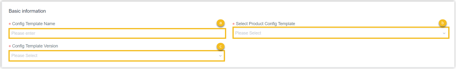
- In the Profile Template Name field, specify a name to help you identify this template.
- In the Select Product Profile Template field, search and select UR32_Profile_Template.
- In the Profile Template Version drop-down list, select the version of the Profile template.
Step 2. Configure the connecting platform
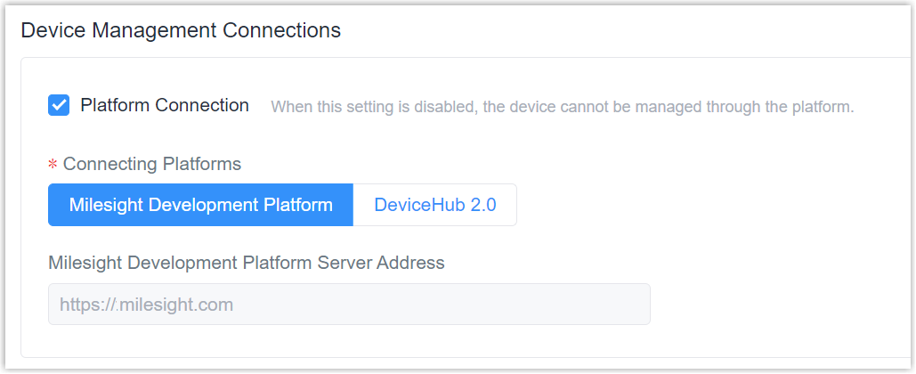
- Select the Generic Configuration tab.
- In the Device Management Connections section, decide
whether to connect the device to Milesight platform for remote management
and configuration.
- Connect the device to Milesight Development Platform
- Retain the default settings.
- Connect the device to Milesight DeviceHub
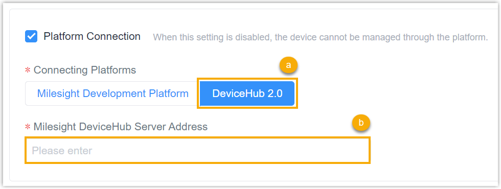
- In the Connecting Platforms field, select DeviceHub 2.0.
- In the Milesight DeviceHub Server Address field, enter the server address of the Milesight DeviceHub.
- Do NOT connect to Milesight platform
- Uncheck the Platform Connection.

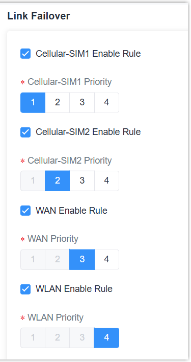
Step 3. Configure the Link Failover Rule
- In the Link Failover section, select the link to use and set the priority
for every link.Note: WLAN interface is only supported when work mode of WLAN is Client.
Step 4. Configure the Ethernet
In the Ethernet section, specify the WAN information.
- Select the connection type.
- Static IP: assign a static IP address, netmask and gateway for Ethernet WAN port.
- DHCP Client: configure Ethernet WAN interface as DHCP Client to obtain IP address automatically.
- PPPoE: configure Ethernet WAN interface as PPPoE client.
- DHCPv6 Client: configure Ethernet WAN interface as DHCP Client to obtain IPv6 address automatically.
- Dual-Stack Lite: use IPv4-in-IPv6 tunneling to send terminal device’s IPv4 packet through a tunnel on the IPv6 access network to the ISP.

-
Specify the Ethernet settings according to the connection type.
Type Settings Static IP IPv4 Address: Set the IPv4 address of the Ethernet port. Netmask: Set the Netmask for Ethernet port. IPv4 Gateway: Set the gateway for Ethernet port's IPv4 address. IPv6 Address: Set the IPv6 address of the Ethernet port. DHCP Client Use Peer DNS: Obtain DNS from DHCP server. PPPoE Username: Set the username provided by your Internet Service Provider (ISP). Password: Set the password provided by your Internet Service Provider (ISP). Link Detection Interval: Set the heartbeat interval for link detection. Max Retries: Set the maximum retry times after it fails to dial up. Use Peer DNS: Obtain DNS from the Internet Service Provider (ISP). DHCPv6 Client Request IPv6-address: Choose the ways to obtain the IPv6 address fromthe DHCPServer. Select from try, force, none. Request prefix length of IPv6: Set the prefix length of IPv6 address which router is expectedto obtain from DHCP Server. Dual-Stack Lite IPv6 Address: Set the IPv6 address of the Ethernet port. IPv6 Gateway: Set the gateway for Ethernet port's IPv6 address. DS-Lite AFTR Address: Set the DS-Lite AFTR server address. Other Settings Primary DNS Server: Set the primary DNS server. Secondary DNS Server: Set the secondary DNS server. MTU: Set the maximum transmission unit. NAT: Enable or disable NAT function. When enabled, a private IP can be translated to a public IP.
Step 5. Configure the Cellular
In the Cellular section, specify the cellular information.

| Setting | Description |
|---|---|
| Protocol Type | Select from IPv4, IPv6 and IPv4/IPv6. |
| APN |
Specify the Access Point Name for cellular dial-up connection provided by local ISP. Please contact cellular operator or search for the Internet to get it. |
| Username |
Specify the username for cellular dial-up connection provided by local ISP. |
| Password | Specify the password for cellular dial-up connection provided by local ISP. |
| Authorization Type |
Select from None, PAP and CHAP. |
| PIN Code |
Specify a 4-8 characters PIN code to unlock the SIM. |
| IPv4 Subnet Mask | Customize the cellular subnet mask. If blank, the device will use thesubnet mask provided by the cellular base station. |
Step 6. Configure the WLAN
In the WLAN section, specify the WLAN information. The WLAN works as AP mode to configure device or works as Client mode to connect to other access points.
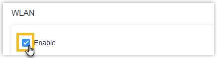
- Click to enable Wi-Fi feature.
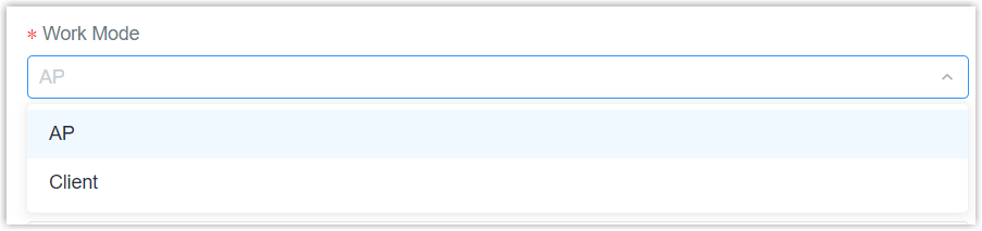
- Select the work mode as AP or Client.
- Specify the information of the Wi-Fi feature when work mode is AP.
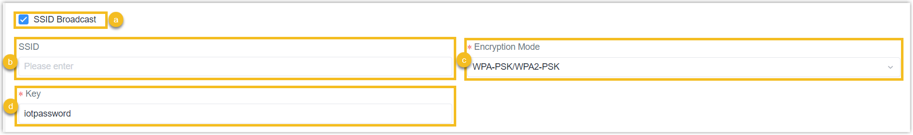
- Enable or disable the SSID Broadcast as required. If disabled, this AP can not be found directly.
- Specify the SSID as needed. The unique name for this device Wi-Fi access point. The default SSID is Router_xxxxxx. (xxxxxx is the last 6 digits of MAC address.)
- Specify the Encryption Mode.
- Specify the Key. The default key is iotpassword.
- Specify the information of the Wi-Fi feature when work mode is
Client.
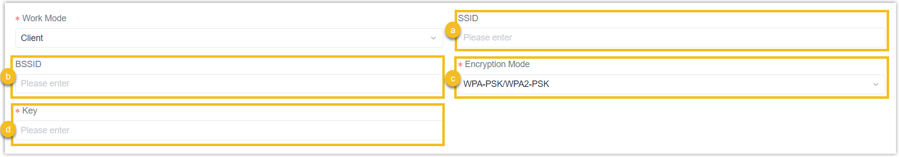
- Specify the SSID of Wi-Fi access point.
- Specify the BSSID of Wi-Fi access point. (Optional)
- Specify the Encryption Mode of Wi-Fi access point.
- Specify the Key of Wi-Fi access point.
Step 7. Configure the DHCP Server
In the DHCP section, enable the DHCP server and specify the DHCP server information.
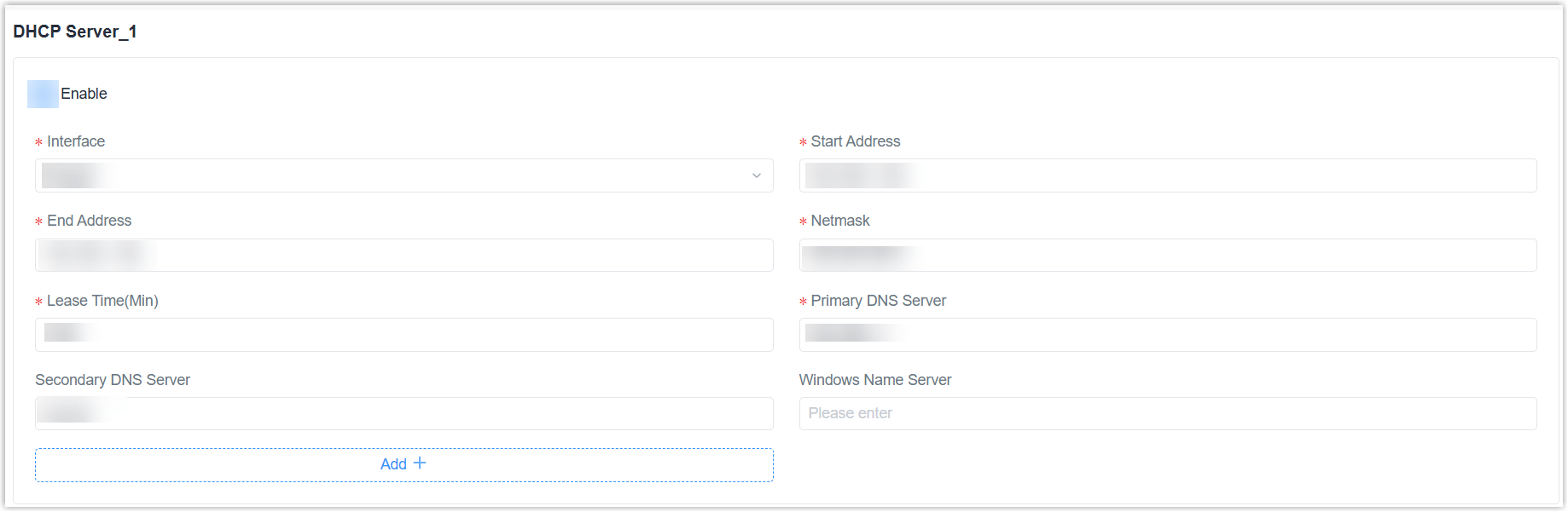
| Setting | Description |
|---|---|
| Interface | Select from Bridge0 and LAN1/WAN. |
| Start Address | Define the beginning of the pool of IP addresses which will be leased to DHCP clients. |
| End Address | Define the end of the pool of IP addresses which will be leased to DHCP clients. |
| Netmask | Define the subnet mask of IPv4 address obtained by DHCP clients from DHCP server. |
| Lease Time (Min) | Set the lease time on which the client can use the IP address obtained from DHCP server. |
| Primary DNS Server | Set the primary DNS server. |
| Secondary DNS Server | Set the secondary DNS server. |
| Windows Name Server | Define the Windows Internet Naming Service obtained by DHCP clients from DHCP sever as needed. |
| Static IP | Assign a static IP address to the device with a specific MAC address. |
Step 8. Configure the Static Routing
In the Static Routing section, add one or more static routing information as required.

| Setting | Description |
|---|---|
| Destination | Specify the destination IP address. |
| Network/Prefix Length | Specify the submask or prefix length of destination address. |
| Interface | Specify the interface through which the data can reach the destination address. |
| Gateway | Specify the IP address of the next router that will be passed by before the input data reaches the destination address. |
| Distance | Specify the priority of this routing. Smaller value refers to higher priority. |
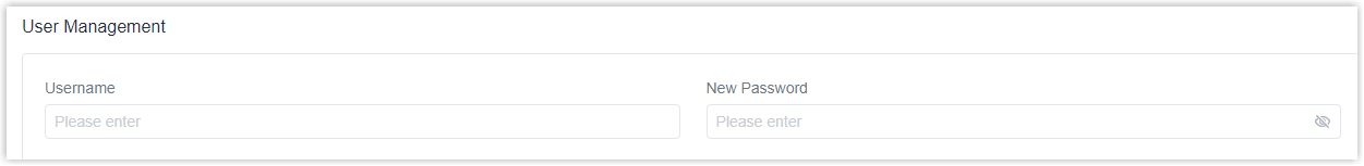
Step 9. Configure the User Management
In the User Management section, you can specify the user name and a new password of the device.
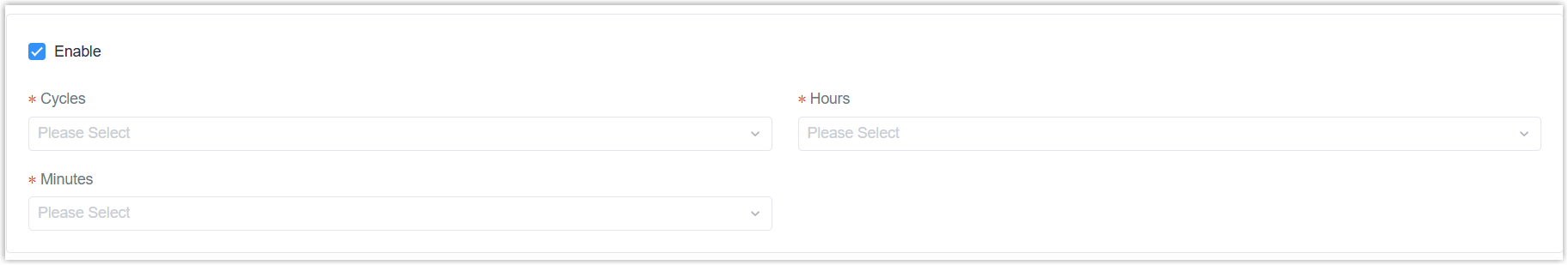
Step 10. Configure the Schedule Reboot
In the Schedule Reboot section, specify whether to enable schedule reboot and the reboot schedules.
Step 11. Configure the DI/DO
- In the DI Setting section, select the DI mode and
specify the DI information.

Setting Description DI Mode Specify the DI mode. - High Level: trigger when the DI changes to high level for duration.
- Low Level: trigger when the DI changes to low level for duration.
- Counter: trigger when the DI meets the condition for the counter value.
Action Specify the action when the DI triggers. - In the DO Setting section, select the DO mode and
specify the DO information.
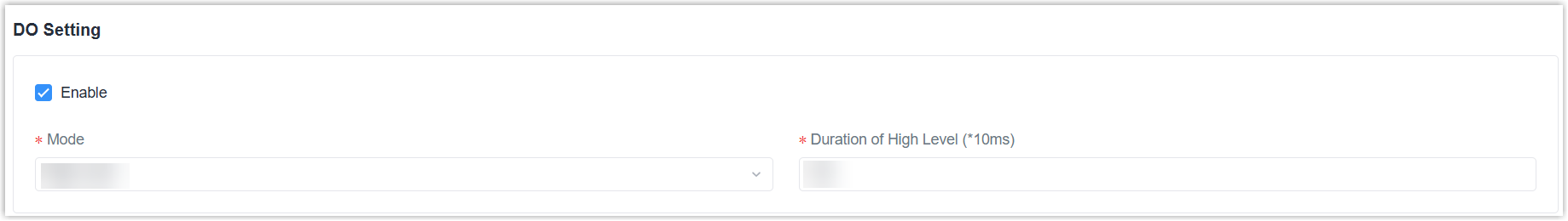
Mode Setting High Level Duration of High Level: Specify the duration to output high level. Low Level Duration of Low Level: Specify the duration to output low level. Pulse Duration of High Level: Specify the duration to output high level in one pulse. Duration of Low Level: Specify the duration to output low level in one pulse. Initial Status: Specify the initial status of DO. The Number of Pulse: Specify the number of pulses the device sends. Custom Initial Status: Specify the initial status of DO.
Step 12. Configure the serial
- In the Serial section, specify the basic serial
settings and select the serial mode.
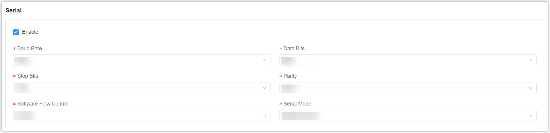
Settings Description Baud Rate Specify these values the same as serial terminal devices. Data Bits Stops Bits Parity Software Flow Control Enable or disable software flow control. Serial Mode Select work mode of the serial port. - DTU Mode: The serial port can establish communication with the remote server/client.
- GPS: Send GPS data to serial port.
- Modbus Client: Work as Modbus client to poll the data from serial devices.
- Modbus Server: Work as Modbus server to wait for polling DI/DO status.
- Select the DTU protocol and specify the information when the serial mode is
DTU Mode.
- Transparent: work as TCP/UDP client to transmit data to server.
- TCP Server: work as TCP server to wait for polling data.
- UDP Server:work as UDP server to wait for polling data.
- Modbus:convert Modbus RTU to Modbus TCP.
DTU Protocol Settings Transparent Protocol: select TCP or UDP. Keepalive Interval: The interval to send heartbeat packet to keep alive. Keepalive Retry Times: When TCP heartbeat times out, the router will resend heartbeat. After it reaches the preset retry times, router will reconnect to TCP server. Packet Size: The maximum sending size of every packet. Serial Frame Interval: The interval to send the serial packets. Reconnect Interval: After connection failure, the device will reconnect to the server at the preset interval. Specific Protocol: By Specific Protocol, the device will be able to connect to the TCP2COM software. Register String/ID:Define the unique ID/string for distinction. Server: Specify the server address and port to send to. Modbus Local port/Listening port: Specify the listening port. Maximum TCP Clients: Specify the maximum number of TCP clients allowed to connect the device which act as a TCP server. Connection Timeout: If the TCP server does not receive any data from the serial device within the connection timeout period, the TCP connection will be broken. Reading Interval: The interval to read remote Modbus channels. Response Timeout: The maximum response time to wait for the replies from serial devices. Maximum Retries: Specify the maximum retry times after failing to read. UDP Server Local port/Listening port: Specify the listening port. Packet Size: The maximum sending size of every packet. Serial Frame Interval: The interval to send the serial packets. TCP Server Local port/Listening port: Specify the listening port. Keepalive Interval: The interval to send heartbeat packet to keep alive. Keepalive Retry Times: When TCP heartbeat times out, the router will resend heartbeat. After it reaches the preset retry times, router will reconnect to TCP server. Packet Size: The maximum sending size of every packet. Serial Frame Interval: The interval to send the serial packets.
Step 13. Configure the System Time
In the System Time section, specify the time settings of the device.

- Specify the Time Zone you are in.
- Select the Sync Type.
- Sync with NTP Server: Specify the NTP Server's IP address or domain name.
- Set up Manually: Specify the date and time directly.
- Specify whether to enable the device to work as a NTP server.
Step 14. Save the custom Profile template
- On the left-bottom of the page, click Save.
- Apply the custom Profile template according to the operation method.
- Web page: Select the Profile template when adding devices.
- API: Do as follow:
- In the Operation column, click
 to download the Profile in
JSON.
to download the Profile in
JSON.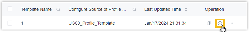
- Include the entire JSON in the API request of Create Configuration Tasks.
- In the Operation column, click